xComputer Info
xComputer is a kind of simulation of a very simple model computer. (It imitates the step-by-step execution of machine language instructions, but not the hardware of a computer.) It does not simiulate any specific, real computer, but is very loosely based on the 6502 processor, which was used in the Commodore 64 computer in the early 1980s, and its design is appropriate to that time frame. The orginal xComputer simulator was written to accompany The Most Complex Machine, a textbook that I published in the 1995. The current version, which runs on a web page, retains the essential features of the original.
A computer stores programs and data in its main memory (or "RAM"). It has a central processing unit (or "CPU") that fetches instructions from memory, one-by-one, and executes each instruction. This is called the fetch-and-execute cycle. In xComputer, a single fetch-and-execute cycle is itself made up of small steps. Each of these little steps performs a very simple operation, such as copying data from one location inside the CPU to another, adding two numbers, or moving information between main memory and the CPU. Each step is accomplished by turning control wires on and off. These control wires are attached to the main memory and to various components in the CPU. A control circuit turns the control wires on and off, based on just a few pieces of information, including the instruction that is being executed and the value of a counter that counts off the little steps of each fetch-and-execute cycle. All the values that the CPU is currently working with are stored in registers, which are small memory units contained within the CPU. The whole process is driven by a clock. Each time the clock ticks, one step of a fetch-and-execute cycle is performed.
That's a very brief description of the fundamental operation of a computer. With some extensions, most of it is still true of all existing computers. The xComputer implements this fundamental operation for a computer with a 1024-location RAM and eight registers. Like any computer, the xComputer has a certain set of machine language instructions that it understands. Machine language instructions are actually binary numbers and are not really meant to be read or written by humans. Programs for the xComputer are therefore usually written in assembly language. An assembly language program must be translated into machine language before it can be executed by a computer. The assembly language for xComputer has 31 different instructions, which are listed below.
The xComputer web page has two main sections. At the top is a text editor where an xComputer assembly language program can be entered. And on the bottom is the xComputer simulator itself.
Above the text area is a popup menu that lists some sample programs that are available. Selecting an item from the popup menu will show the corresponding program in the text editor. The web page attempts to load eight sample programs into the popup menu. You can learn a lot about xComputer and its assembly language by reading the first five or six sample programs.
If you want to create a new program of your own, select "[New Program]" from the pop-up menu. The text area will be cleared, and you can enter your your program there. The "Save" button lets you save the program from the text area to a local text file on your computer. The "Load" button lets you select a text file on from your computer to be loaded into the text area. In most browsers, saving and loading files will use file save/open dialogs similar to those used in other programs. (Some browsers still use an older kind of file handling. In those browsers, saving a file will look just like downloading a file from the Internet, and loading a file will look like uploading a file to the Internet.) Saving and loading files is new in November, 2023.
Beneath the text editor is a "Load Program into xComputer" button. Click that button to load the program into the simulator. But if there are syntax errors in the program, an error message will be displayed below the text editor instead. In the case of an error, the input cursor in the text editor will be moved to the point in the program where the error was found. Only the first syntax error in the program is found and reported. (For undefined word errors, the error occurs at the end of the program, when no definition has been found for the word.)
The xComputer Simulator
The point of the simulator is to illustrate the step-by-step operation of a computer as it executes a program. When the web page is loaded, it displays a text box where programs can be entered and edited, with the actual simulator at the bottom of the page. The editor should show a sample program, with more sample programs available in a pop-up menu above the editor. The text of each sample program includes information about the program and about xComputer. You can also enter your own programs. To start a new program, just select '[New program]' from the popup menu. To translate the program in the editor into machine language and load the program into xComputer's memory, click the "Load Program into xComputer" button. Here, to give you an idea of what assembly programs look like, is a really trivial program that adds 7 and 18 and puts the answer into memory location number 10:
             LOD-C 7
             ADD-C 18
             STO 10
The simulator is divided into several sections: a "Control" area, a set of "Registers", a set of "Control Wires", and two views of "Memory". One view of memory is a scrolling list that displays 1024 memory locations, numbered from 0 to 1023. Each location contains a 16-bit binary number that can be interpreted either as data or as a machine language instruction. The second view of memory, on the far right, is a graphical display of the same information. (See the sample program named "Graphics View of Memory" in the pop-up menu of program.) The Registers section shows eight registers that are components in the xComputer's Central Processing Unit. The registers are explained below. The Controls are for interacting with and controlling the xComputer. Finally, the Control Wires section lists xComputer's 26 control wires. The name of a control wire is highlighted when that control wire is on (except that there is no highlighting when the program is being executed at fast speed).
Suppose that you have some assembly language program in the program editor. Before xComputer can do anything with that program, it must be translated into machine language and put into xComputer's main memory. To do this for a program in the editor, click the "Load Program into xComputer" button. If an error is found in the program, an error message will be displayed below the editor. If the program contains no errors, it will be put into xComputer's memory, You can then run the program or step through it, as described below.
The question remains, exactly what sort of thing can be stored in memory? The first thing you need to understand is that what is really in each main memory location and in each register is a binary number. Any other form of information must be represented somehow as a binary number. The same binary number can represent different values, depending on how it is interpreted. In xComputer, there are several formats for entering and viewing the values that are actually represented internally as binary numbers:
- Integer — any whole number in the range -32768 to 32767.
- Unsigned integer — any whole number in the range from 0 to 65535. (Thus, you can actually use any number from -32768 to 65535. However, numbers from -32768 to -1 and from 32768 to 65535 are ambiguously represented by the same binary numbers.)
- Assembly language instruction — any legal assembly language instruction for xComputer, such as "LOD-C 17". (See the list below.)
- ASCII characters — a single quote, followed by any typeable character or a pair of characters (except for carriage return). The quote just marks this as ASCII data. For example: 'DE
- Hexadecimal number — a dollar sign ($) followed by from one to four hexadecimal digits. For example: $A73D
- Binary number — a B (upper or lower case) followed by from 1 to 16 zeros and ones. For example: B110010111010
So, a binary number in memory can represent several different things. The xComputer simulation allows you to select how you want to view the binay numbers that are stored in memory. Select the view that you want from the pop-up menu above the memory display. The "Instructions", "Integers", "Unsigned Ints", "Binary", and "ASCII" display styles correspond to some of the data types listed above. (In the ASCII display style, two characters are shown in each memory location. Non-printing characters are shown as ASCII code numbers enclosed between < and >. For example, <#17> represents the character with ASCII code number 17.) There is a similar pop-up menu in the Registers area to select how you want to view the contents of the registers.
Running a Program
A program consists of a series of instructions stored in memory. The computer fetches instructions one-by-one and executes them. The program counter register (or "PC") tells the computer which address to go to in memory for the next instruction. When you want to run a program, you should always first check that the value in the PC register is the address of the location that contains the first instruction of the program. You can set the value in the PC to zero using the "Set PC=0" button. To set the PC to some other value, type the value into the "Addr" box and then click on the "Addr To PC" button. Note that when you use the "Load Program into xComputer" button to put a program into memory, the PC will automatically be set to zero at the same time. However, after you run the program once, you would have to reset the PC manually if you want to run it again.
Once you have set the PC, there are three different ways to run the program:
- Click the "Step" button. This performs one of the several small steps that make up each fetch-and-execute cycle. You have to click on this between five and ten times, depending on the instruction, to execute each instruction. Note that the names of the control wires that were turned on for the step are highlighted. Any registers affected by the step are also highlighted.
- Click the "Cycle" button. This is meant to perform one complete fetch-and-execute cycle. More exactly, it performs "step" operations until the value in the COUNT register is zero, marking the end of one fetch-and-execute cycle. At that point, the instruction in the IR register has just beeen executed. You don't see the individual steps, and there is no highlighting of registers or control wire names.
- Click the "Run" button. This makes the computer execute instructions continually, like a real computer. The "Run" button changes into a "Stop" button, which you can use to stop the computer. The computer will also stop if it executes a HLT instruction. The speed at which the computer runs is determined by a pop-up menu just below the run button. At "Fast Run Speed", the contents of registers are updated, but control wires are not highlighted. At the "Fastest Run Speed", neither registers nor control wires are updated. The "Fast Run Speed" executes about 60 instructions per second, while "Fastest Run Speed" executes about 600 per second.
Registers and Control Wires
The xComputer has eight registers. A register is a memory unit that holds one binary number. Different registers holds different numbers of bits. Each of the registers has a role to play in fetching and executing instructions. Here is a short description of the purpose of each register:
- ADDR register: The address register is a 16-bit register that holds the address of a location in memory. Whenever data is read from or written to memory, this is the address that is used. (If you turn on the "Autoscroll" checkbox, below the scrolling memory display, then any time the value in ADDR changes, the memory will be scrolled to ensure that that memory location is visible in the display (except when the computer is running at fast speed.)
- PC register: The program counter is a 10-bit register that contains the address in memory of the next program instruction that is scheduled to be executed. The PC is ordinarily incremented by 1 during each fetch-and-execute cycle. Its value can be also be changed by the execution of a jump instruction, which tells the computer to jump to a different location in the program and continue execution from there.
- IR register: The instruction register is a 16-bit register that holds a program instruction while it is being executed. This is where an instruction is put when it is fetched from memory.
- COUNT register: This is a 4-bit register that counts off the steps in each fetch-and-execute cycle. At the beginning of each step, its value is incremented by one. The last step of the cycle resets this register to zero, so that the next cycle can begin.
- AC register: The accumulator is a 16-bit register that holds a number that is being used in the current calculation. When a number is loaded from memory, it is put in the AC. When a number is stored into memory, the value is taken from the AC. When a number is "added", it is added to the value currently in the AC, and the result is put back into the AC. Etc.
- FLAG register: This is a 1-bit register that can give extra information about a calculation. For example, when two 16-bit numbers are added, the final "carry" into the 17-th column is stored in the FLAG register. When a shift operation is performed on the AC, the extra bit that is shifted off the end is placed into the FLAG register.
- X and Y registers: These are 16-bit registers that hold numbers that are to be used in a calculation. For example, when two numbers are to be added, they are placed into X and Y. (The Y register is also used as a temporary storage place in a few cases.)
The X and Y registers are connected to the inputs of an Arithmetic-Logic Unit, or "ALU", which does all the arithmetic and logical calculations in the computer. The outputs of the ALU are connected to the AC and to the FLAG register. (The ALU is not shown in the xComputer simulation.)
The components of the computer — including the main memory, the registers, the clock, and the ALU — are controlled by turning wires on and off. These wires are connected to various components of the computer, and they control the operation of those components. It is these " control wires" that make the steps of the fetch-and-execute cycle happen. For example, in step #1 of each fetch-and-execute cycle, the control wire named "Load-ADDR-from_PC" is turned on. This causes the number stored in the PC — which is the location of the instruction that is to be fetched — to be copied into the ADDR register — where it sets up the main memory for reading from that location. The purposes of most of the wires are clear from their names. (The first seven wires, whose names start with "Select-", are connected to the ALU. The ALU can perform several different calculations. The Select wires are used to tell it which calculation it should do.)
The Assembly Language of xComputer
An assembly language program is simply a way of specifying a sequence of 16-bit binary numbers to be stored in the computer's memory. As such, it can include any of the data items described above: Assembly language instructions, numbers in the range -32768 to 65536, hexadecimal numbers (up to four digits, preceded by $), binary numbers (up to 16 bits, preceded by B or b), and ASCII characters (one or two characters, preceded by a single left quote mark).
The legal instructions are listed below. An instruction consists of a two- or three-character code, such as LOD, OR, and HLT. Since upper and lower case letters are not distinguished, these could also be written as lod, or, and hlt. In some cases, this instruction code can be followed by an addressing mode, indicated by "-C" for "constant" addressing mode and by "-I" for "indirect" addressing mode. The addressing mode indicates how the data for the instruction is to be used. For example, ADD-C 17 indicates that the constant, 17, is to be added to the number in the accumulator, while ADD 17 indicates that a number is to be read from memory location 17 and added to the number in the accumulator, and ADD-I 17 indicates that location 17 holds a memory address and the number from that address is to be added to the value in the accumulator.
As you can see, the data for the instruction simply follows the instruction. It must be on the same line. You can't split instructions over two lines, and you can't have more than one instruction on a line. Not all instructions need data. If you provide data for an instruction that doesn't need it, it is legal, but the data will be ignored when the instruction is executed. The data for an instruction is a 10-bit binary number. It can be given in any of the following forms:
- a number between 0 and 1023,
- a binary number between B0 and B1111111111,
- a hexadecimal number between $0 and $3FF,
- a single ASCII character, preceded by a left single quote mark,
- a label name.
The last possibility — a label name — brings us to a whole new aspect of assembly language. An assembly language program can contain more than just a sequence of items representing 16-bit numbers. It can contain other things to make programming easier by letting the computer do more of the work. A label is a name that stands for a number. A label represents a 10-bit binary value and can appear anywhere in the program where such a value could be used, that is, as the data part of an instruction or as a stand-alone item on a line by itself. When the program is translated, the label is replaced by the number it represents. A label is given a value by using it to label one of the 16-bit items that make up the program. To define a label in this way, the label name must be the first thing on the line, followed by a colon (:) and the item that it labels. The value of the label is the address of the location in memory that contains that item. For example, the following program adds up all the numbers from 1 to 50:
               lod-c 1       ; Initialize number to contain 1.
               sto number
               lod-c 0       ; Initialize sum to contain 0.
               sto sum
         next: lod sum       ; Add current value of number to sum.
               add number
               sto sum
               lod number    ; Add one to the value of number.
               inc
               sto number
               sub-c 51      ; Subtract 51 from the number, which is still in AC.
               jmz done      ; If the answer is zero, jump to "done".
               jmp next      ; Otherwise, jump to "next" to continue the computation.
         done: hlt           ; Halt.
          sum: 0             ; (The zeros are place-holders to reserve memory
       number: 0             ;     locations for sum and number.)
In this program, next, done, sum, and number are labels. The labels next and done refer to locations that hold instructions. The labels sum and number refer to locations that hold data for the program. The programmer can work with the instructions and data without having to work out the actual location numbers. (This program also illustrates comments. Anything on a line after a semicolon (;) is treated as a comment and is ignored by the computer.)
There are a few more things you can do in an assembly language program. A program item can be preceded by a number followed by a #. This is a repetition count and is the same as typing the item the specified number of times. For example, "25# 17" puts a 17 in each of the next 25 memory locations. "4# SHL" is equivalent to four SHL instructions in a row.
Ordinarily, a program is loaded into consecutive memory locations starting at location 0. However, you can specify where loading is to take place by using the character @ followed by an address. For example, "@100" specifies that the next item is to go into memory location 100. (Items following that one will then go into location 101, 102, etc.) You might use this feature to put subroutines or data at specific points in memory.
You can use the special word "data" to represent the binary number zero. This is meant to provide a more meaningful way to reserve memory locations for storing data. For example, the line "num: data", which is equivalent to "num: 0", reserves a space in memory and assigns it the label num.
Finally, you can store a string of ASCII characters into consecutive memory locations by using a string. A string is just a series of characters enclosed between double quotes, such as "Hello World!". When the computer encounters a string in a program, it stores the characters in consecutive memory locations, one per location.
Not every binary number represents a legal assembly language instruction. When xComputer tries to execute such an instruction, it simply ignores it. That is, illegal instructions are treated as "no-ops"; they perform "no operation".
List of Assembly Language Instructions
Here is a complete list of the assembly language instructions for xComputer. In this listing, "X" is data for the instruction; it must represent a 10-bit binary number in any of the five forms listed above.
- ADD X — Add the number in memory location number X to the AC
- ADD-C X — Add the actual number X to the AC
- ADD-I X — Let Y be the contents of memory location number X, and then add the number in location number Y to the AC
- SUB X — Subtract the number in memory location number X from the AC
- SUB-C X — Subtract the number X from the AC
- SUB-I X —Let Y be the contents of memory location number X, and then subtract the number in location number Y from the AC
- AND X — Bitwise AND the number in memory location number X with the AC
- AND-C X — Bitwise AND the number X with the AC
- AND-I X — Let Y be the contents of memory location number X, and then bitwise AND the number in location number Y with the AC
- OR X — Bitwise OR the number in memory location number X with the AC
- OR-C X — Bitwise OR the number X with the AC
- OR-I X — Let Y be the contents of memory location number X, and then bitwise OR the number in location number Y with the AC
- NOT — Apply a bitwise NOT to the AC
- INC — Add 1 to the AC
- DEC — Subtract 1 from the AC
- SHL — Shift the AC left one bit
- SHR — Shift the AC right one bit
- LOD X — Load the number from memory location X into the AC
- LOD-C X — Load the number X into the AC
- LOD-I X — Let Y be the contents of memory location X, and then load the number from location number Y into the AC
- STO X — Store the value in AC into memory location X
- STO-I X — Let Y be the contents of memory location X, and then store the value in AC into location Y
- JMP X — Jump to location X (that is, store X into the PC, so that the next instruction will be loaded from X)
- JMP-I X — Let Y be the contents of memory location X, and then jump to location Y
- JMZ X — If the value in the AC is zero, then jump to location X
- JMZ-I X — If the value in the AC is zero, then let Y be the contents of memory location X, and then jump to location Y
- JMN X — If the value in the AC is negative, then jump to location X (where "negative" really means that the leftmost bit in the number is 1)
- JMN-I X —If the value in the AC is negative, then let Y be the contents of memory location X, and jump to location Y
- JMF X — If the value in the FLAG register is one, then jump to location X
- JMF-I X — If the value in the FLAG register is one, then let Y be the contents of memory location X, and then jump to location Y
- HLT — Halt. That is, stop the xComputer by turning on the Stop-Clock control wire
A Logisim Simulation of xComputer
Logisim is a free program that can simulate logic circuits. Logisim is a fairly old program, but is very good at what it does. It is written in Java, so to use it, you need to have a Java runtime environment installed on your computer. You need to download logisim.jar, which is the executable jar file that contains the program. And you need to know how to run an executable jar file (basically, enter java -jar logisim.jar on the command line in the directory that contains the file logisim.jar). Once you have Logisim running, you can find extensive information about it in its "Help" menu.
I decided to make a simulation of the xComputer model computer in Logisim, to make sure that it could actually be done. The simulation is in a file, xComputer.circ, that you can download and open in Logisim, using the "Open" command in the Logisim "File" menu. If you want to see what the xComputer simulation looks like in Logisim, see xComputer-in-Logisim.png. Even if you don't want to try the simulation, the picture is a nice illustration of how all the components of xComputer are wired together.
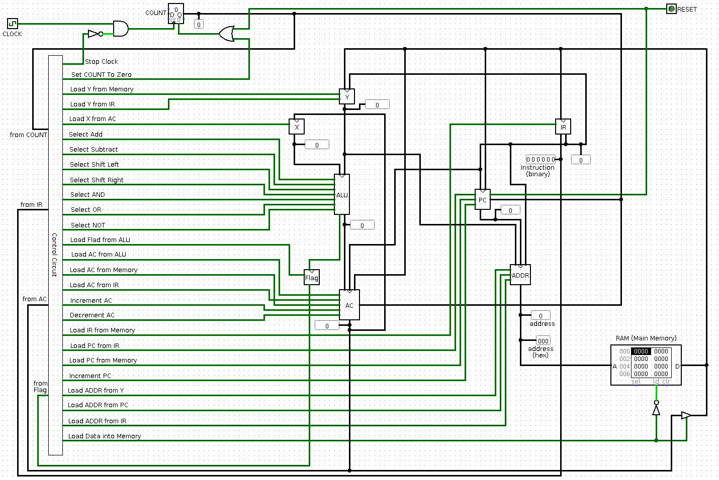
This simulation does not really serve any purpose, except to illustrate that it can be done. But if you would like to try it, you will want load an xComputer program into the simulation's RAM (that is, its main Memory). As an example, the file TheBasics-for-Logisim-RAM.txt contains the first sample program from the xComputer app, in the syntax required for a Logisim memory file. To use it, download the file, open the xComputer simulation in Logisim, right-click the RAM component at the lower right in the simulation, and select "Load Image" from the popup menu. Click the Clock component at the upper right of the simulation (using Logisim's "Poke" tool) to perform one step in the execution of the program. (Make sure "Simulation Enabled" is checked in the "Simulate" menu. Use "Ticks Enabled" in that menu to run the simulation automatically.) Note that the xComputer control wires that are on for that step will be shown in a brighter green.
The "Grab Memory for Logisim" button at the very bottom of the xComputer app can be used to extract the current contents of the xComputer memory from the app, in the format that is needed for loading into Logisim. A popup dialog will appear with a text area containing the contents of memory. You can copy-and-paste from the text area into a text editor and save the data in a plain text file. The popup dialog can be closed by clicking the "Dismiss!" button or by pressing the Escape key.